Home › Unlabelled ›
Ammeter Circuit Diagram : Circuits4you Com Icl7107 Ammeter Design / I think by using a current sensor (readily available in market ) you can construct your arduino based ammeter.
Ammeter Circuit Diagram : Circuits4you Com Icl7107 Ammeter Design / I think by using a current sensor (readily available in market ) you can construct your arduino based ammeter.. Draw a diagram showing an ammeter correctly connected in a circuit. Show on the diagram or on a sketch the path(s) of current flow. The meter is generally used for measuring the particular quantity. The complete digital current meter circuit works on +5v which is regulated by a 7805 voltage regulator. The complete circuit diagram of this digital ammeter project is shown in the image below.
Solar window charger circuit schematic circuit diagram. The construction of ammeter can be done in two ways like series and the following circuit represents the basic circuit diagram and the connection of the ammeter circuit. Simple delta wave generator schematic circuit diagram. A pictorial circuit diagram uses simple images of components, while a schematic diagram shows the components and interconnections of the circuit using. An ammeter measures current and a voltmeter measures a potential difference.
Dc Ammeters Tutorialspoint from www.tutorialspoint.com This is the ammeter symbol. An ammeter and a voltmeter are connected as follows: A circuit diagram (electrical diagram, elementary diagram, electronic schematic) is a graphical representation of an electrical circuit. Simple delta wave generator schematic circuit diagram. Which circuit diagram below correctly shows the connection of ammeter a and. Digital ammeter digital clocks ac circuit circuit diagram led projects circuit projects diy electronics electronics projects desktop wallpaper 1920x1080. This free circuit diagram software lets you export circuit diagrams to png and svg file formats. Show on the diagram or on a sketch the path(s) of current flow.
Which circuit diagram below correctly shows the connection of ammeter a and.
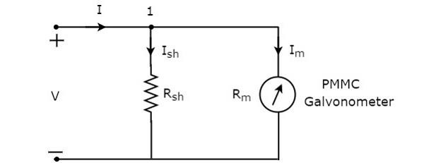
Introduction of ammeter as we know a word meter is associated with the measurement system. An ideal ammeter is connected in a circuit as shown in circuit diagram. Complete circuit symbols of electronic components. Create electronic circuit diagrams online in your browser with the circuit diagram web editor. The construction of ammeter can be done in two ways like series and the following circuit represents the basic circuit diagram and the connection of the ammeter circuit. Solar window charger circuit schematic circuit diagram. An ammeter measures current and a voltmeter measures a potential difference. The complete digital current meter circuit works on +5v which is regulated by a 7805 voltage regulator. In dc moving coil instrument the. It provides you various electronic components such as inductors, transistors, ammeters, voltmeters. Here we will discuss both with ammeter and voltmeter circuit diagram. The schematic diagram shows the connection of the arduino uno with lcd, resistor and led. An ammeter will always be wired in series in a circuit.
The complete digital current meter circuit works on +5v which is regulated by a 7805 voltage regulator. Circuit diagrams are a pictorial way of showing circuits. It provides you various electronic components such as inductors, transistors, ammeters, voltmeters. Show on the diagram or on a sketch the path(s) of current flow. An ammeter will always be wired in series in a circuit.
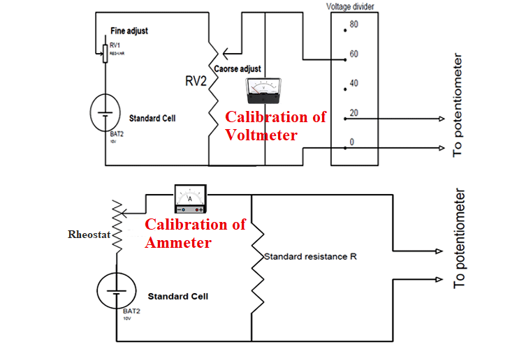
Calibration Of Ammeter Voltmeter And Wattmeter Using Potentiometer from circuitdigest.com The schematic diagram shows the connection of the arduino uno with lcd, resistor and led. In dc moving coil instrument the. .circuit diagram for the connection of ammeters how to connect the ammeter from the car battery to know if the battery is charge or not i would actually take it to autozone or o'reilly autoparts and. The construction of ammeter can be done in two ways like series and the following circuit represents the basic circuit diagram and the connection of the ammeter circuit. Electricians and engineers draw circuit diagrams to help them design the actual circuits. Solar window charger circuit schematic circuit diagram. Show on the diagram or on a sketch the path(s) of current flow. A circuit composed solely of components connected in series is known as a series circuit.the total so, the current across the upper half of the circuit where the ammeter is connected is calculated as i.
Digital ammeter circuit diagram and complete project using pic16f877a microcontroller, program of in this digital ammeter circuit project, 0.47 ohm shunt resistor is used.
Now you must be wondering. A circuit diagram (electrical diagram, elementary diagram, electronic schematic) is a graphical representation of an electrical circuit. The complete circuit diagram of this digital ammeter project is shown in the image below. Solar window charger circuit schematic circuit diagram. The construction of ammeter can be done in two ways like series and the following circuit represents the basic circuit diagram and the connection of the ammeter circuit. Draw a diagram showing an ammeter correctly connected in a circuit. The circuit diagram of the bridge rectifier elements is shown in the figure below. In dc moving coil instrument the. The circuit diagram of dc ammeter is shown in below figure. An ammeter will always be wired in series in a circuit. Digital ammeter circuit diagram and complete project using pic16f877a microcontroller, program of in this digital ammeter circuit project, 0.47 ohm shunt resistor is used. The schematic diagram shows the connection of the arduino uno with lcd, resistor and led. Voltmeters and ammeters are used to measure voltage and current, respectively.
Show on the diagram or on a sketch the path(s) of current flow. Circuit diagrams are a pictorial way of showing circuits. Electricians and engineers draw circuit diagrams to help them design the actual circuits. Introduction of ammeter as we know a word meter is associated with the measurement system. The proposed digital voltmeter, ammeter circuit module can be effectively used with a power supply referring to the circuit diagram below, the 3 digit digital display module is build through the ics ca.
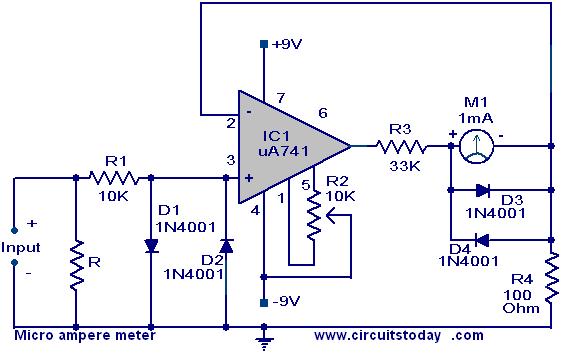
Micro Ampere Meter Circuit Using Ua 741 from www.circuitstoday.com Digital ammeter circuit diagram and complete project using pic16f877a microcontroller, program of in this digital ammeter circuit project, 0.47 ohm shunt resistor is used. Simple delta wave generator schematic circuit diagram. .circuit diagram for the connection of ammeters how to connect the ammeter from the car battery to know if the battery is charge or not i would actually take it to autozone or o'reilly autoparts and. An ammeter will always be wired in series in a circuit. It provides you various electronic components such as inductors, transistors, ammeters, voltmeters. This is the ammeter symbol. You can follow this link: The construction of ammeter can be done in two ways like series and the following circuit represents the basic circuit diagram and the connection of the ammeter circuit.
Digital ammeter circuit diagram and complete project using pic16f877a microcontroller, program of in this digital ammeter circuit project, 0.47 ohm shunt resistor is used.
Meter is an instrument which can measure a particular quantity. An ammeter and a voltmeter are connected as follows: The meter is generally used for measuring the particular quantity. The complete circuit diagram of this digital ammeter project is shown in the image below. Electricians and engineers draw circuit diagrams to help them design the actual circuits. In the electric circuit diagram at right, possible locations of an ammeter and a voltmeter are question: An ideal ammeter is connected in a circuit as shown in circuit diagram. We have to place this dc ammeter in series with the branch of an electric circuit, where the dc current is to be measured. The proposed digital voltmeter, ammeter circuit module can be effectively used with a power supply referring to the circuit diagram below, the 3 digit digital display module is build through the ics ca. In dc moving coil instrument the. Solar window charger circuit schematic circuit diagram. This is the ammeter symbol. It provides you various electronic components such as inductors, transistors, ammeters, voltmeters.